Serverless WireGuard
Diode supports serverless secure WireGuard - peer to peer WireGuard that doesn’t require a star topology server, and that doesn’t have vendor risk on the control plane.
It leverages:
- Standard WireGuard clients and software
- Blockchain-based encrypted control plane
- Diode Network’s UDP relays
This article demonstrates how to connect two or more devices via WireGuard through the Diode Network, even if none of them have a publicly accessible IP address.
#1) Create Perimeter in the ZTNA Console
First, go to https://ztna.diode.io, login/signup, and create a Perimeter and give it a name (e.g. Wireguard Server Config).
After you create a Perimeter, the Perimeter’s address will be shown at the top of your page:
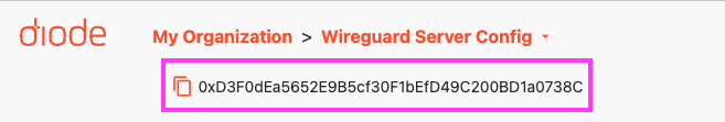
Click the copy icon to copy the Perimeter address.
In the next step, you will either provide it to the users who will be using the WireGuard network, or you will use it yourself if you will be configuring devices.
#2) Install the Diode CLI on the systems
The devices/systems that will be using WireGuard should install the Diode CLI from https://diode.io/download/#cli . Optionally you can build it from source per the README at https://github.com/diodechain/diode_client.
Once installed, they should invoke the CLI so that in joins the Perimeter:
diode join <perimeter address>
Example:
diode join 0xD3F0dEa5652E9B5cf30F1bEfD49C200BD1a0738C
If the device they are running on is a headed device, they can also enable the tray icon with “-tray=true” (e.g. diode -tray=true join 0xD3F0dEa5652E9B5cf30F1bEfD49C200BD1a0738C)
When the CLI runs, it will print out the system’s Client address. You need to gather the different Client addresses from each device, and add each as an Asset in your Perimeter so that the device is able to cryptographically “join” the perimeter and acquire control plane/configuration information.
NOTE: This step will be made easier in the future because the CLI will send a “connect” log to the Perimeter’s logging service that allows the Perimeter manager to see Client addresses (and relevant system information) of new devices that would like to connect, and to click-create an Asset if they would like the client to connect.
#Configure the ZTNA Console
In the ZTNA Console, you can configure the WireGuard configuration for each asset with its WireGuard Interface section, and also can create a tag that has their WireGuard Peer information. You can name the WireGuard Peer information tag “Connect to <asset name>”.
Then, you can choose which Assets you’d like to connect to which other Assets by assigning the “Connect to” tags to each Asset.
Example: Connect two Assets (A and B) to each other via Wireguard
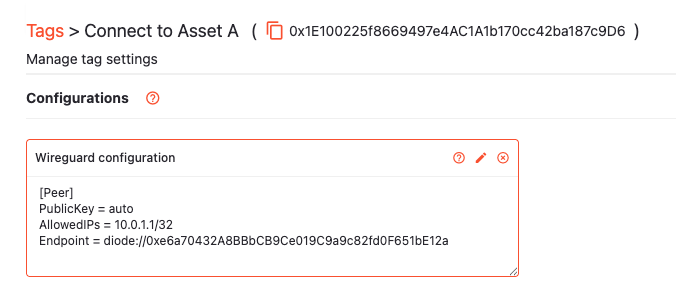
Asset A Client ID: 0xe6a70432A8BBbCB9Ce019C9a9c82fd0F651bE12a
Asset B Client ID: 0x13a45432A8BBbCB9Ce019C9a9c82fd0F651Eb131
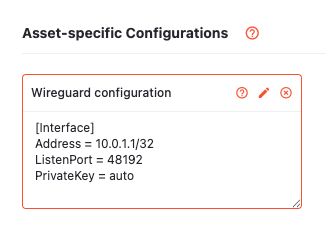
For each Asset, add a “WireGuard” configuration with an [Interface] section containing the internal IP address you’d like it to have.
For example, for an internal IP address of 10.0.1.1/32, Asset A’s configuration would look like:
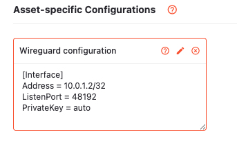
For an internal IP address of 10.0.1.2/32, Asset B’s configuration would look like:
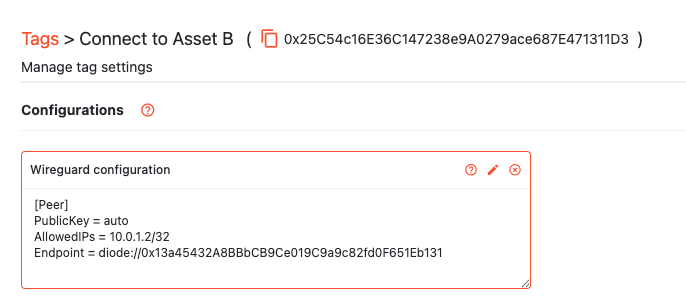
Then, create a tag called “Connect to Asset A” with a WireGuard configuration that specifies a [Peer] section pointing to your Asset A:
Create a similar tag that specifies the Asset B peer:
NOTE: The tag creation steps will be made easier in the near future - upon creation of a WireGuard configuration on an asset, a tag will be automatically created that you can use to connect other Assets to the one you just created.
Then, you can simply add the tag “Connect to Asset B” to Asset A, and add the tag “Connect to Asset A” to Asset B. They will auto-configure and join a shared WireGuard network.